
Planning and Design Criteria
2.1.0 PLANNING AND DESIGN CRITERIA
TNB refers to Grid Code for Peninsula Malaysia and Distribution Code for Peninsula Malaysia, Sabah & F.T. Labuan in developing the connection system or supply infrastructure needs which are included in this section. Both documents are publicly available at the Energy Commission’s website.
2.1.1 Steady-State Supply Voltage Performance
a) Steady-State Voltage Fluctuation under Normal Condition
Under normal condition, when all circuit elements are in service, the distribution network including the points before the Users Connection Point shall be planned to be maintained as is Table 1-1 below:-
| Voltage Level | % Variation | |
| 400V and 230V | -6% & +10% | |
| 6.6kV, 11kV, 22kV, 33kV | +/- 5% | |
| 132kV dan 275kV | +/-5% | |
| 500kV | +/-5% | |
Table 1-1: Steady -state voltage level regulation limits under normal conditions
b) Steady-State Voltage Fluctuation under Contingency Condition
Under contingency condition, when one or more circuit elements are on outage, the power frequency steady-state voltage at all points in the distributor’s distribution system including the points before the consumer metering must be planned to be maintained as follows:
| Voltage Level | % Variation | |
| 400V and 230V | +/- 10% | |
| 6.6kV, 11kV, 22kV, 33kV | +/- 10% | |
| 132kV dan 275kV | +/-10% | |
| 500kV | +/- 10% | |
Table 1-2: Steady-State Voltage Regulation Limits under Contingency Condition
2.1.2 Supply Security Level
Supply security of a distribution system network defines the availability of supply to consumers following the occurrence of supply interruption. Systems and necessary network management infrastructure may be designed to meet any of the standardized security level definitions currently adopted by TNB as indicated in Table 1-3.
2.1.2.1 Adopted Security Level Definitions For TNB Distribution System
| Security Level | Average Restoration Period | |
| Level 1 | Less than 5 seconds | |
| Level 2 | Less than 15 minutes | |
| Level 3 | Less than 4 hours | |
| Level 4 | Less than 24 hours | |
Table 1-3: Security Levels for Distribution Network
2.1.2.2 Supply Security Level to Consumers
In accordance to Guaranteed Service Level (GSL), supplies to consumers at voltage levels of 11kV, 22kV and 33kV normally be provided with alternative circuits and/or other facilities such that supplies shall be restored within a period of up to 4 hours (Security Level 3), except due to natural disaster or weather. In exceptional instances where alternative feedback source is not available consumers at voltage levels of 11kV, 22kV and 33kV may have supply restoration time extended beyond 4 hours.
For supplies at 230V and 400V, the restoration period may vary beyond 3 hours depending on the type of network fault.
Time to restore electricity supply following major incident on grid or transmission system except due to natural disaster, and causing partial blackout, restoration time shall be within 8 hours and for total blackout situation it shall be within 18 hours.
2.1.2.3 Request for Higher Supply Security Level
However, TNB can design the supply scheme to meet higher security level requirement of individual consumer or group of consumers. All additional costs involved in providing the higher security level shall be borne fully by the consumer.
2.1.3 Power Quality
2.1.3.1 Power Quality Requirement
2.1.3.1.1 TNB supplies electricity by the alternating current (ac) system with system frequency of 50 Hz with specified regulated voltage levels. The ranges of voltage regulations available are explained in section 2.1.1 of this guideline.
2.1.3.1.2 TNB shall supply electricity to the main incoming terminals or point of common couplings (PCC) between the consumers and TNB with general electromagnetic environment statistics as indicated in standards IEC 61000-2-4 and IEC/TR 61000-2-8.
2.1.3.1.3 TNB does not guarantee that the electricity supply will not be interrupted or its frequency and voltage will not fluctuate outside the ranges stated in section 2.1.1. TNB will take the necessary steps to enhance the system reliability and security to all customers. The reliability of the supply system is evaluated and monitored by the Supply Average Interruption Duration Index (SAIDI). And the duration of supply restoration will be dependent upon the determined security levels as stated in section 2.1.2.1.
2.1.3.1.4 The supply voltage and frequency may fluctuate for short duration outside the voltage ranges stated in section 2.1.1 due to the following:
a) When TNB takes the necessary action for safety reasons
b) When TNB carries out critical maintenance and repairs on the network components,
c) When matters outside the control of TNB i.e. external influences, are the causes of the supply problem; and
d) Other circumstances that cause supply to be interrupted or cause voltage and frequency to fluctuate.
2.1.3.1.5 The consumer shall ensure that all equipment to be connected to TNB supply system is electromagnetically compatible with the electromagnetic environment declared by TNB.
2.1.3.2 Requirements of Consumer’s Equipment
2.1.3.2.1 TNB specifies requirement that the consumer’s must comply in order to minimize the impact of the electromagnetic disturbances that may exist in the power system for example voltage sags, transients/surges etc.
2.1.3.2.2 The requirements are:-
| Type of Disturbance | Indices |
Acceptable permissible values at point of common coupling (PCC) |
Reference Document |
||
|
Voltage Step Change |
ΔV % | 1% - Frequent starting/switching and/or disconnection of load. |
UK’s Engineering Recommendation P28 |
||
| 3% - Infrequent single starting/ switching or disconnection of Load – once in two hours or more hours. | |||||
|
6% - Starting/switching once or twice a year. |
|||||
| Voltage Fluctuation and Flicker | Absolute Short Term Flicker Severity (Pst) | 1.0 (at 132kV and below) |
UK’s Engineering Recommendation P28 |
||
| 0.8 (Above 132kV) | |||||
| Absolute Long Term Flicker Severity (Plt) | 0.8 (at 132kV and below) | ||||
| 0.6 (Above 132kV) | |||||
| Harmonic Distortion2 | Total Harmonic Distortion Voltage (THDV) % | 5% at ≤ 400 Volt |
Engineering Recommendation ER G5/4 |
||
| 4% at 11kV to 22kV | |||||
| 3% at 33kV | |||||
| 3% at 132kV | |||||
| Voltage Unbalance | Negative Phase Sequence Voltage % | 2% for 1 minute |
UK’s Engineering Recommendation P29 |
||
| Voltage sag | Immunity requirement |
All critical equipment & processes must be immune to voltage sag. |
IEC 61000-4-11 & IEC 61000-4-34 |
||
Table 1-4: TNB Power Quality Requirements
2.1.3.2.3 It is the responsibility of the consumer to ensure that his voltage sensitive equipment is able to function continuously through unanticipated voltage sags and transients/surges, caused when the system is subject to external interference such as lightning, 3rd party cable damage, other consumer’s equipment fault, TNB equipment fault etc.
2.1.3.2.4 The consumer must select equipment that are immune to both voltage sags, transients/surges etc. Consumers should request from equipment manufacturers, equipment that cancomply with the electromagnetic compatibility (EMC) requirement of IEC 61000 and ENGR.
2.1.3.2.5 The recommended standards to refer for evaluating equipment’s sensitivities and identifying immunity solutions to voltage sags and transient/surge are IEC 61000-4-11/34 and IEC 61000-4-5.
2.1.3.2.6 Overall the customer’s plant and apparatus shall be compatible with the basic insulation levels (BIL) define in this handbook.
2.1.3.2.7 Guidelines on some immunity measures against voltage sags can be referred to TNB Power Quality Guidebook
2.1.3.3 Declaration to Power Quality Requirement
2.1.3.3.1 The consumer is required to declare his equipment compatibility and compliance with regards to the required power quality standard using the Power Quality Compliance Declaration Form in Appendix 7.
2.1.4 Short-Circuit Levels
TNB network are design and operated in order to remain within the limits of short-circuit levels as in Item 1.4.5 of Supply Application Section. TNB equipment design is specified to the same Short Circuit rating. Consumer’s equipment at the point of interface or part of the interconnection design shall also comply with the minimum Short Circuit rating. TNB may provide indicative or prospective fault level in terms of X/R at the interface point with consumer, if so required for detailed installation design.
2.1.5 Protection Requirements
2.1.5.1 Basic Requirements
In all cases, the basic requirement is that the consumer’s arrangements for protection at the connection point, including types of equipment and protection settings, shall comply with TNB practices, and be as TNB specifies during the application for supply process. This is especially critical for MV and HV consumers.
2.1.5.2 Specific Requirements
Consumers shall take into consideration the following specific protection practices of TNB in designing their installation:
a) Maximum clearance times (from fault current inception to fault clearing) shall be within the limits established by TNB in their short circuit rating policy.
b) Auto-reclosing or sequential switching features may be used on TNB’s distribution system.TNB will provide details on the operating sequence utilised for the supplies on the proposed installation so the consumer can plan for this in the design and protection of his facility.
c) On some of TNB’s distribution systems, e.g. lateral feeders or tee-offs, certain types of faults may cause disconnection of one phase only of a three-phase supply.
d) The following additional protection features are recommended to consumers with special requirements:
i. For voltage sensitive consumer, it is advisable to install over/under voltage protection scheme with a suitable time delay scheme.
ii. A suitable time delay scheme must be installed for the under voltage relay that governs the changeover system for the generator and other voltage sensitive equipment.
iii. And it is not recommended to install an over/ under voltage protection scheme at the incomer VCB to factory.
iv. Consumer intending to have more than 1 incoming feeder shall take into consideration supply option with Automatic Transfer Scheme (ATS). However, all technical requirements shall be discussed and agreed by both TNB and consumer.
All costs and installation work are to be borne by consumer.
2.1.5.3 Protection System Evaluation Process
Consumer's installation to be supplied at 11kV and above shall provide the appropriate and matching protection scheme to support the desired operation of the designed supply scheme. The reliability of the equipment, protective devices and protection systems being deployed at the consumer connection or interface points may affect the reliability of TNB’s supply system.
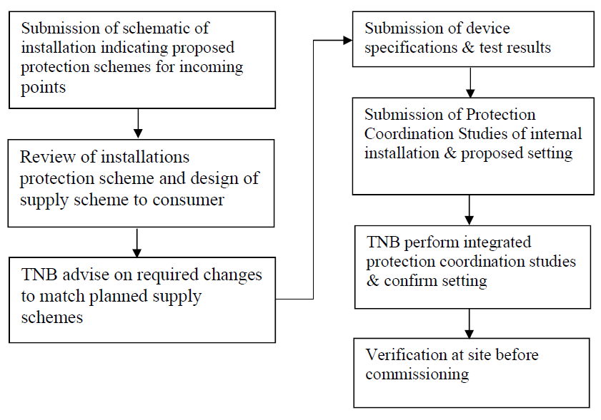
Figure 1-1 above illustrates the steps involved in the evaluation of protection schemes.
X
Demand Estimation
2.2.0 DEMAND ESTIMATION
Supply schemes and networks are to be adequately designed or dimensioned to meet initial and growth of consumer individual and group maximum demand.
The demand estimates are based upon load declared by consumer and TNB’s own information on load profile characteristics for various consumer classes. Range of values are given as demand profile are known to varies according to geographical location of consumers around the TNB service areas in Peninsular Malaysia.
Fairly accurate assessment of individual and group demand of consumers are critical for correct dimensioning of network or facilities in meeting the initial and future demand of consumers as imposed on the network.
2.2.1 Demand Estimates For Consumer Sub-Classes Or Premises
Table 2-1 and Table 2-2 indicates the typical ranges of maximum demand for domestic and shoplots or shop-houses respectively. These values shall be subjected to revisions based upon of latest results load profiling studies.
| No. | Type Of Premises | Rural (kW) |
Suburban (kW) |
Urban (kW) |
|
| 1 | Low cost flats, single storey terrace, studio apartment ( < 600 sq ft) | 1.5 | 2.0 | 3.0 | |
| 2 | Double storey terrace or apartment | 3.0 | 4.0 | 5.0 | |
| 3 | Single storey, semidetached | 3.0 | 5.0 | 7.0 | |
| 4 | Double storey, semidetached | 5 | 7.0 | 10 | |
| 5 | Single storey bungalow & three-room condominium | 5 | 7.0 | 10 | |
| 6 | Double storey bungalow & luxury condominium | 8.0 | 12 | 15 | |
Table 2-1: Range of maximum demand (M.D) for domestic consumer sub-classes or premises
| No. | Type Of Premises | Rural (kW) |
Suburban (kW) |
Urban (kW) |
|
| 1 | Single storey shop house | 5 | 10 | 15 | |
| 2 | Double storey shop house | 15 | 20 | 25 | |
| 3 | Three storey shop house | 20 | 30 | 35 | |
| 4 | Four storey shop house | 25 | 35 | 45 | |
| 5 | Five storey shop house | 30 | 40 | 55 | |
Table 2-2: Range of maximum demand (M.D) for types of shop-houses
*The above MD range is meant for reference as the minimum value. MD declared by consultants must be accompanied with the connected load and design calculations of the development.
*For commercial more than 3 storey supply must be underground
For underground system, every lot of shop house is required to have individual service cable termination into the shop lots meter panel.
2.2.2 Demand Estimates Of Mixed Development Area.
Accurate determination of the maximum possible demand for a newly proposed development is critical in the effective long-term planning of supply network within the specific area. Adequate land areas for transmission main intakes (PMU 275kV, 132/33kV, 132/22kV, 132/11kV), major distribution stations (PPU 33/11kV, 22/11kV), sub-stations (PE 11/.4kV, 22/.4kV), feeder pillars, underground cable and overhead line routes will have to be allocated at the layout approval stage by the relevant authorities.
The total demand will indicate the supply voltage and target network configuration for the whole development area. Network facilities will be developed in phases in tandem with physical development.
Site selections for PMU, PPU, sub-stations and feeder routes are determined at development plan stage to achieve optimal technical performance of network and costs based on the planned target network.
2.2.3 Group Coincident Factor
Group coincident factor is applied in the computation of unit demand and group demand. The typical values for coincident factors for different groups of consumers are as tabulated in the table below:
| Consumer Groups | Coincident Factors | |
| Residential | 0.90 | |
| Commercial | 0.87 | |
| Industrial | 0.79 | |
| Residential + Commercial | 0.79 | |
| Residential + Industrial | 0.87 | |
| Commercial + Industrial | 0.79 | |
| Mixed Group | 0.75 | |
Supply Schemes
2.3.0 SUPPLY SCHEMES
Based upon consumer’s declared demand level and required security level, supply schemes to consumers are appropriately designed to meet these requirements as discussed in section 1.
2.3.1 Maximum Demand Levels And Supply Schemes
The table below indicates the minimum supply schemes for various demand levels of individual consumers.
Consumers with the following M.D shall adhere to the minimum supply scheme.
| M.D ranges of individual consumer | Supply voltage | Minimum supply scheme | |
| Up to 12 kVA | 230V | Single phase overhead or underground services from existing LV network | |
|
>12kVA to 100kVA (Non-Domestic) |
400V | Three phase overhead or underground cable service from existing LV network subject to system capability study by TNB | |
|
Up to 100 kVA (Domestic) |
400V | Three phase overhead or underground cable service from existing LV network subject to system capability study by TNB | |
| >100kVA to 350kVA | 400V | Underground cable service from feeder pillar or a new/existing substation, subject to system capability study by TNB | |
| >350 kVA to 1000kVA | 400V | Direct underground cable service from new substation | |
| 1000kVA up to <5000kVA | 11kV | Directly fed through TNB 11kV switching station. An additional PPU land may need to be allocated subject to system capability study by TNB | |
| 1000kVA up to 10000kVA | 22kV | Directly fed through TNB 22kV switching station An additional PPU land may need to be allocated subject to system capability study by TNB' | |
| 5000kVA to 25000kVA | 33kV | Directly fed through TNB 33kV switching station An additional PMU land may need to be allocated subject to system capability study by TNB' | |
| 25,000kVA to <100,000kVA |
132kV, 275 kV |
Directly fed through TNB 132kV or 275kV substation respectively. TNB shall reserve the absolute right to provide alternative arrangements after taking into consideration the location, economic and system security factor | |
| 100,000kVA and above | 275 kV | Directly fed through TNB 275kV substation. TNB shall reserve the absolute right to provide alternative arrangements after taking into consideration the location, economic and system security factor | |
Table 3-1: Minimum supply schemes for various M.D levels
The above minimum supply scheme for the consumer is the minimum level of supply scheme shall be adhered by the consumer. If upon system analysis & study conducted by TNB, a higher supply scheme is required to give quality supply to the consumers, the later prevails.
The table below indicates the requirement of substations for various demand levels of single development.(more than 1 consumer), total maximum demand including all phases / parcels in the development.
| M.D ranges of single development | Substations requirement | |
| Up to 350kVA | A new 11/0.4kV substation may be required, subject to system capability study by TNB | |
| >350 kVA to <1000kVA | A new 11/0.4kV substation is required | |
| 1000kVA up to <5000kVA | 11/0.4kV and/or 11kV substations is required. A new PPU may be required, subject to system capability study by TNB | |
| 1000kVA up to 10000kVA | 22/0.4kV and/or 22kV substations is required. A new PPU may be required, subject to system capability study by TNB | |
| 5000kVA to 25000kVA | 11/0.4kV and/or 11kV and/or 33kV substations and/or PPU is required. A new PMU may be required subject to system capability study by TNB | |
| Above 25000kVA | 11/0.4kV and/or 11kV and/or 33kV substations and/or PPUs and PMUs. 132kV is required. A new PMU 275kV may be required subject to system capability study by TNB | |
Table 3-2: Requirement of substations for single development
For new housing development with solar rooftop, the substation requirement shall comply to Smart Community Infrastructure (SCI) as stated in Section 2.4.0.
2.3.2 Substation Categories, Type & Design
2.3.2.1 Sub-Station Categories
a. Transmission Main Intake (Pencawang Masuk Utama-PMU)
Transmission Main Intake is the interconnection point of 132kV or 275kV to the distribution network. The standard voltage transformations provided at the PMU are as follows:-
- 275/132kV
- 132/33kV
-
132/11kV
b. Main Distribution Sub-Station (Pencawang Pembahagian Utama- PPU)
Main Distribution Sub-station is normally applicable to 33kV for interconnecting 33kV networks with 11kV networks. It provides capacity injection into 11kV network through a standardized transformation of 33/11kV.
c. Main Switching Station (Stesyen Suis Utama- SSU)
SSU at 33kV, 22kV and 11kV are established to serve the following function:-
- To supply a dedicated bulk consumer ( 33kV, 22kV, 11kV)
- To provide bulk capacity injection or transfer from a PMU/PPU to a load center for further localized distribution.
d. Distribution Substation (Pencawang Elektrik – P/E)
Distribution substations are capacity injection points from 11kV, 22kV and sometimes 33kV systems to the low voltage network (400V, 230V). Typical capacity ratings are 1000kVA, 750kVA, 500kVA and 300kVA.
Note: Service cable from the TNB 33 kV and 11 kV substation (whereby the metering room is within TNB’s control area) to the consumer substation shall be laid and maintain by TNB if the service cable is within 30 metres. For service cable above 30 meters shall be bourne by the consumer.
Conventional Substation
Conventional substation designs are of indoor type (equipment housed in a permanent building) and out-door type (ground-mounted or pole-mounted). Standard layout c/w M & E design of SSU 11kV and 11/0. 4kV sub-station is available at TNB offices, and publicly available in TNB website: Substation Design Booklet.
Compact Substation
Compact substation 11/0.4kV is being considered as standard substation for installation at new
development with following guideline:
- Maximum size of compact substation 11/.4kV for new housing development (domestic consumers) is 500kVA.
- Maximum size of compact substation 11/.4kV for new commercial and industrial development is 1000kVA, subject to availability of matching size metering kiosk for singlecustomer connection.
- Compact substation to be placed close to the load center.
- Compact substation not to be placed at the corners of one development, and to be away from the sewarage plant.
- Compact substation cannot be placed close to each other to ensure efficient load distribution to the consumers.
The selection of compact substation placement is subject to TNB system planning and operational requirement. Compact substation is not suitable in circumstances as follow that requires indoor type substation:
- Places identified for circuit breaker installation including places of important and sensitive.
- Places with more than two 11kV feeder connections.
- MSC status area
- Within the attached type substation building
Main Distribution Substation / Main Switching Substation.
Appropriate distribution network design to ensure security of supply & restoration time to consumers:
- If the development is more than 5MVA, Main Distribution Substation (PPU) and / or Main Switching Station (SSU) shall be provided by the developer within the housing development to support 11kV network connection to respective distribution substation.
-
For development that is less than 5MVA, requirement of Main Distribution Substation (PPU) and / or Main Switching Station (SSU) depends on the existing network configuration & constraints.
2.3.2.2 Land Or Building Size Requirements For Substations
| Substation Category | Type | Land Size (Average Dimensions – NOT inclusive of Land Setback Requirements) |
Building Size (Average Dimensions) |
|
|
Transmission Main Intake/Pencawang Masuk Utama (PMU): |
Gas Insulated Switchgear (GIS) Without outdoor switchyard |
(a) 60.0m x 80.0m (b) 140 m x 75m |
Customized design to match land size building bylaws | |
|
Transmission Main Intake/Pencawang Masuk Utama (PMU): |
Air Insulated Switchgear (AIS) With outdoor switchyard |
(a)130.m x 130.0m (b) 160 m x 150 m |
Customized design to match land size building bylaws | |
|
Main Distribution Substation (PPU) |
Indoor type | 46.0m x 46.0m | Customized design to match land size building by laws (refer to Substation Design Booklet) | |
|
Main Switching Substation (SSU) |
Indoor | 30.0m x 30.0m | Customized design to match land size building by laws (refer to Substation Design Booklet) | |
|
Main Switching Station (SSU) |
Conventional – Stand alone |
Land size to take into consideration of Uniform Building By-Law’s set-back requirement
|
7.6 m x 5.7 m | |
|
Main Switching Station (SSU) |
Conventional – Stand alone | 7.0 m x 6.0 m | ||
|
Distribution Substation (P/E) |
Conventional – Stand alone |
7.6 m x 5.7 m | ||
|
(b) Double chamber |
10.6 m x 5.7 m | |||
|
(c) Compact substation |
7.0m x 4.0m | NA | ||
|
Distribution Substation (P/E) with CESS |
Conventional – Stand alone |
Please refer to attachment PE single Chamber with CESS | ||
|
b) Double chamber |
Please refer to attachment PE Double Chamber with CESS | |||
Table 3-3: Land and building size requirements for substations
Note: Set-back requirement (subject to respective local authority’s latest requirement) :
- JKR : On all Federal and State Routes: 20.1m (66ft) from center of road + 15.0m (50ft) for service road to substation site.
- Local Authority/City Council/Jabatan Perancang Bandar : 6.1m (20ft) for building line + other requirements as requisitioned by Local Authority/City Council/Jabatan Perancang Bandar.
-
LLM (Malaysian Highway Authority): As requisitioned by LLM.
The establishment of transmission main intake also requires the allocation and acquisition of right of way or wayleaves for the transmission lines. Depending on the specific design of each PMU, the overall right of way or wayleaves requirements may be different.
Developers of large-scale development areas, depending on the estimated demand shall be required to allocate land for any or a combination of sub-stations categories, wayleaves or right of way for 132kV/275kV lines. These requirements will be specified by TNB upon submission of tentative layout plans and load estimates for the whole development area during pre-consultation stage.
2.3.2.3 Type of fire fighting System for the Substation
Consumer is required to install fire fighting system in substations of following types:
- Attached type substation
- Transmission Main Intake (PMU) / Main Distribution Substation (PPU) / Main Switching Station (SSU)
-
Standalone substation with generator room attached.
The fire fighting system for use in substation must be certified by TNB with valid “Certificate of Product Acceptance” (Sijil Guna Pakai – SGP) by TNB.
The fire fighting system must be designed to suit the substation and meets the following criteria:
- Shall be a complete system consists of suppression system and alarm and detection system.
- Must be certified and tested by certified test agencies (UL, FM, LPCB or equivalent)
- Must be verified by Bomba as a total flooding system.
- Must be designed to suit and use in substation
- Extinguishing Agent must be clean and residual-free and must not be corrosive on electrical and electronic equipment.
- Environmentally friendly as determined by Kyoto Protocol, Montreal Protocol and EPA SNAP List / EPEE
- Occupant safe
- Must be suitable for extinguishing all Classes of fire (Class A, B, C and E)
-
Fire fighting system shall be given a warranty of 5 years from date of commissioning by installer that covers all of above and in the event of accidental discharge occurs, warrantee shall cover damages on TNB equipment.
Fire fighting system installed at TNB installation shall be approved according to standards given below :-
| 1. Suppression system | ||
| a. MS ISO 14520 | - Single phase overhead or underground services from existing LV network | |
| b. NFPA 2001 | - Clean Agent Fire Extinguishing System | |
| c. NFPA 2010 | - Aerosol System | |
| 2. Alarm and detection system | ||
| a. ISO 7240 | - Fire Detection and Alarm System | |
| b. NFPA 72 | - Standards for Protective Signalling | |
| c. EN 54 | - Standardization for All Component Parts of a Fire System | |
All maintenance work shall be conducted by the consumer or owner of building based on standard NFPA: 2001 and ISO14520.
Exhaust fan with thermostat control is required to be installed at all attached substations (SSU 11kV and P/E 11/0.4kV) as well.
2.3.3 Standard And Special Feature Design Schemes
Standard features of supply schemes are categorized as those typical design schemes for individual or consumer groups or classes. Typical cases are as follows:-
- Supply scheme supplying domestic premises is predominantly through overhead systems and conventional sub-station.
- Bulk supply consumers at 11kV and above, are normally supplied via one or two service cables depending on the MD required. All system will be designed based on Security Level 3 or Security Level 4. If higher security level is required, or another dedicated cable is required by the consumer, then it shall be considered as special features.
- Consumers with MSC status or applying for MSC status requiring higher security level, the installation to meet the higher security level shall be considered as special features.
-
For any special features, consumer is required to bear the cost of equipment, installation and any related scope of work.
Connection Guideline for Distributed Energy Resources
2.4.0 CONNECTION GUIDELINE FOR DISTRIBUTED ENERGY RESOURCES
The Connection Guideline for Distributed Energy Resources shall be in accordance with the Renewable Energy Act 2011 and its subsidiary legislation and regulatory guidelines.
Smart Community Infrastructure (SCI) shall be integrated into network design to facilitate the seamless incorporation of distributed energy resources, ensuring optimised supply–demand balancing and maintaining the stability and reliability of the distribution system. For new housing developments with aggregated solar rooftop capacity, the provision of Voltage Regulating Distribution Transformers (VRDT) and/or Community Energy Storage Systems (CESS) shall be required as part of the network planning and design standards.
Developers of the above development shall allocate the necessary land area and substations to accommodate CESS based on:
- Table 3-3: Land and building size requirements for substations in Section 2.3.2.2 Land Or Building Size Requirements For Substations.
-
Substations For Smart Community Infrastructure (SCI).
Developer shall bear additional cost associated with SCI under special features.
X