General Requirements
3.1.0 GENERAL REQUIREMENTS
All the necessary meters for measuring the import or export of electricity shall be provided and maintained by TNB. The customer shall ensure the point at which every supply line shall terminate in any premise shall be accessible to TNB’s personnel.
At any point in the premises at which supply line or lines terminate, the developer/consumer shall provide the meter board or metering panel according to TNB’s specifications for the installation of meter and their accessories. TNB may change any meter and its accessories or their positions in any premise as deemed necessary at any time for purposes of
maintenance and meter reading.
The Consumer shall ensure that the 3G signal strength or any other mode of communication that is approved by TNB in the metering room or meter location is adequate or sufficient for effective communication of Remote Meter Reading (“RMR”). The Customer shall obtain the advice from TNB on the minimum signal strength of -77dBm and above.
For low voltage supply without metering CT, the metering scheme is divided into 3
-
Single Phase Whole Current Supply
This metering scheme applies to individual domestic and non-domestic consumers including housing area.
-
Three Phase Whole Current Supply
This metering scheme applies to individual domestic and non-domestic consumers including housing area.
-
Group Metering for Single Phase and Three Phase Whole Current Supply
This metering scheme applies to high, medium and low-rise apartment, commercial premises, hawkers’ centre/food court/food stalls and shop lots.
For low voltage supply requiring metering CT, TNB shall provide low voltage CTs for the meter installation. The CTs shall be of the single ratio and single purpose type.
For medium voltage consumers, CTs and VTs will be provided and installed by TNB at TNB's outgoing switchgear. However for situation whereby CTs and VTs could not be provided by TNB, CTs and VTs shall be provided and installed by consumer which should fulfil the requirements below:
- The metering CTs shall be subjected to testing by TNB
- The passed test certificates for the metering VTs from an accredited laboratory shall be submitted
- Pre-commissioning test must be carried out for VTs and CTs by consumer and witnessed by TNB representative
For high voltage consumers, where the CTs are incorporated in switchgear panels, the consumer shall provide the metering CTs and VTs according to TNB’s specifications and fulfil the requirement below:
- Factory Acceptance Test (FAT) for CTs and VTs must be conducted and witnessed by TNB representative.
- The passed test certificates for the metering CTs and VTs from an accredited laboratory shall be submitted.
- Pre-commissioning test must be carried out for VTs and CTs by consumer and witnessed by TNB representative.
The Electrical Consultant/Registered Electrical Contractor shall ensure clear understanding of TNB metering requirements as detailed below. Should there be any doubt, he should consult the TNB Distribution Network Division Local Office.
Customers participating in New Enhanced Dispatch Agreement (NEDA) programme shall
- Agree all data declared in the portals (such as TNBTWeb/Market Participants Interface etc.) are valid for settlement purposes.
- Install separate metering systems for the import and export energy if the export capacity is lower than 5% of the declared import demand.
- Install separate metering systems for the import and export energy if the export capacity is higher than 100% of the declared import demand.
The metering guidelines are subjected to change from time to time.
XSingle Phase Whole Current Supply
3.2.0 SINGLE PHASE WHOLE CURRENT SUPPLY
3.2.1 Voltage And Current Rating
The voltage supply shall be 230 V. The normal current rating of the electronic meter shall be 10 A - 100 A. The consumer / developer is advised to consult TNB Distribution Network Division Local Office for any enquiries
3.2.2 Location of Meter Position
- The meter board which accommodates TNB’s service cut-out, meters and other auxiliary equipment shall, as far as is practical, be located near the termination of the service line and facing the main entrance of the premises and has ease of accessibility to TNB’s personnel.
- For meter located at the premises, the consumers / developer shall provide meter board as shown in Appendix 10, Drawing No. 2A.
- For housing area with individual gate post, the meter shall be placed at the gate post. Access to meters placed at gate posts shall be from the front only. The design and pecification for the meter panel, meter and accessory arrangement at the gate post is shown in Appendix 9, Drawing No. 1A, 1A(i), 1A(ii).
- Where it is necessary to terminate the service line in a position outside the premise and exposed to the weather, a suitable weatherproof, well - ventilated box with clear glass cover approved by TNB shall be provided by the consumer at his own expense to house the cable termination and meter board, as per TNB’s specifications Appendix 12, Drawing 4A and 5A.
- Consumers whose nature of business involve very dusty or dirty environment shall be required to provide outdoor meter panel to protect the meter installation.
- Group metering for multi tenanted consumers or open commercial outlets shall be addressed Section 3.4.0.
- Meter and their accessories shall be installed only in clean and dry location not exposed to the weather or mechanical injury, free from vibration and not exposed to direct sunlight and rain.
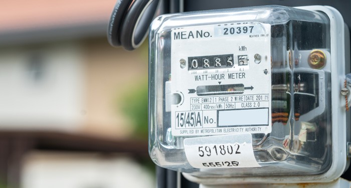
3.2.3 Height Of Meter Position
i. The height of the meter board in the consumer’s premise at the wall facing the main entrance shall be between 1.75m (top of the meter) to 1.85m above ground level as illustrated in the pictures below:

The top of the meter board at the gate post shall be 1.5 m above ground level.
3.2.4 Meter Board
-
The meter board shall be:
- Any hard wood chemically treated against attack by termites (Plywood or chipboard or PVC or PE is NOT allowed).
- Fibre board / plate with minimum thickness of 5.0 mm. The diagram of the board is shown in Appendix 10, Drawing No 2A.
- The arrangement for the meter, cut out, termination wires and the recommended size of the board is shown in Appendix 11, Drawing No. 3A and 3B.
- All board shall be rigidly fixed by a minimum of 5 fixing screws where one screw shall be at the center of the meter. The length of the screw at the center of the meter board must be long enough to penetrate the wall.
- The consumer’s main switches and accessories are not allowed to be installed on the same board.
- In the case of outdoor meter installations at poles for e.g. temporary supply or in mining areas, the recommended meter box is shown in Appendix 13, Drawing No. 5A.
3.2.5 Wiring Arrangement
- The size of meter cables shall be at minimum 10 mm sq. and shall not exceed 25 mm sq. according to the current rating of the meter which is 10 A – 100 A.
- Other than meter installation in risers, the wiring at the meter board shall be on the surface.
- For new installations, the applicant/user must provide wiring from cut-outs and neutral link to meter
X
Three Phase Whole Current Supply
3.3.0 THREE PHASE WHOLE CURRENT SUPPLY
3.3.1 Voltage and Current Rating
The voltage supply shall be 400 V. The normal current rating of the meter shall be 10 A-100A. The consumer/developer is advised to consult the TNB Distribution Network Division Local Office.
3.3.2 Location of Meter Position
The requirements given in 2.2 (i) – (viii) applies for the locations of three phase meter position.
3.3.3 Height of Meter Position
The requirements given in 2.3 (i) – (ii) applies for the height of three phase meter.
3.3.4 Meter Board
i. The recommended size and arrangement of the three phase meter, cut-outs and neutral link for the overhead and underground service is as shown in Appendix 14, Drawing No. 6A – 6C respectively.
ii. The requirements given in 2.4 apply for the three phase meter board.
3.3.5 Wiring Arrangement
i. The requirement given in 2.5 (i) – (ii) also applies for the three phase wiring arrangement.
ii. Other than meter installation in risers, the wiring at the meter board shall be on the surface. For external wiring, please refer to Appendix 15 Drawing No. 7A, 7B and 7C.
XGroup Metering for Single Phase and Three Phase Whole Current Supply
3.4.0 GROUP METERING FOR SINGLE PHASE AND THREE PHASE WHOLE CURRENT SUPPLY
3.4.1 Location and Height of Meter Position
a) High, Medium & Low Rise Apartment
i. In domestic multi-tenanted premises up to 5 storeys, all meters shall be grouped at ground floor in a dedicated metering room or steel netting meter cage.
ii. In domestic multi-tenanted premises above 5 storeys, all meters shall be grouped in dedicated metering room or steel netting meter cage at each floor of the tenants metering. There may be more than one group of metering location at each floor.
iii. The individual meter shall be properly and eligibly labelled with permanent metal plate and riveted to meter panel to indicate clearly the meter supplying to the respective consumer.
iv. The height from the top of the meter panel shall not exceed 2.1m and the bottom shall be above 0.3m from the ground. There shall be working space of 1 m in front the metering panel.
v. In the above requirements, all excess to the dedicated metering room or steel netting meter cage shall be equipped with hinge for locking facility by TNB.
b) Commercial Premises (excluding shop lots)
Multi tenanted commercial premises taking bulk supply shall have the meters installed following clause 5.0 or 6.0, whichever relevant.
If the multitenant commercial premises are taking individual supply to landlord and tenants, the metering arrangement, locations and position shall be similar to clause 4.1.
c) Hawker Centre / Food Court / Food Stall
i. Location of Meter Position
- For Hawker Centre / Food Court / Food Stall centralized group metering, shall be located at the dedicated metering room or steel netting meter cage or end of each row, outside the premises, in a weather proof and ventilated panel/area which is suitable for meter installation and meter reading as per TNB’s specifications. The meter panel or box shall be rigidly and vertically mounted.
- The recommended size and arrangement of the meters, cut outs, and neutral link is as shown in Appendix 16, Drawing No 8A – 8C for single phase group metering and Appendix 17, Drawing No 9B – 9D for three phase group metering.
ii. Mounting of Meter
- The individual meter shall be properly and eligibly labelled with permanent metal plate and riveted to meter panel to indicate clearly the meter supplying to the respective consumer.
- The height from the top of the meter panel shall not exceed 2.1m and the bottom shall be above 0.3m from the ground. There shall be working space of 1 m in front the metering panel.
- In the above requirements, all excess to the dedicated metering room or steel netting meter cage shall be equipped with hinge for locking facility by TNB.
d) Shop Lots
i. Location and Height of Meter Position
- For shop-lots, all meters shall be grouped at ground floor, front wall of the shops in a dedicated metering compartment. The design and specification of shop lots meter panel is shown in Appendix 16 & 17.
ii. Wiring Arrangement
- The requirement given in 2.5 (i) – (ii) also applies for the three wiring arrangement.
- For external wiring, please refer to Appendix 15 Drawing No 7A, 7B and 7C.
3.4.2 Metering Panel
i. The metering panel can be of mild steel or other TNB approved material and of thickness not less than 1.5 mm.
ii. The recommended size and arrangement of the meters, cut-outs, and neutral link is as shown in Appendix 16, Drawing No. 8A – 8C for single phase group metering and Appendix 17, Drawing No. 9B – 9D for three phase group metering.
iii. The holes for the termination wire to the meters shall have appropriate bushings to prevent the wires from being damaged.
iv. In the case of meter box with a cover, the metal plate on which the meters are mounted as well as the cover shall have minimum two metal hinges to enable it to be swung open for at least 90o.
v. The wiring arrangement shall follow:
- Single phase – Please refer to paragraph 3.2.5
- Three phase – Please refer to paragraph 3.3.5
LVCT Metering
3.5.0 LVCT METERING
LV consumers taking more than 100A per phase shall require current transformers for the metering scheme.
3.5.1 Location Of Meter Position
i. Consumer shall provide an accessible space for the metering installation separate from the main switchboard nearest to the source of the TNB supply i.e. TNB Substation, feeder pillar and etc.
ii. The Consumer shall ensure that the 3G signal strength or any other mode of communication that is approved by TNB in the metering room or meter location is adequate or sufficient for effective communication of Remote Meter Reading (“RMR”). The Customer shall obtain the advice from TNB on the minimum signal strength of -77dBm and above.
iii. The maximum distance of the cable from the CTs to the meter panel allowable is shown in Table 1 below. Prior approval for location of the metering panel shall first be obtained from TNB.
Table 1
|
CT Burden VA |
Secondary Rated Current A |
Cross Connection of Conductor mm2 |
Maximum Distance Allowable m |
|
|
7.5 7.5 |
5 5 |
2.5 4.0 |
12.0 20.0 |
|
Where meter burden for current circuit is: L.V. = 0.5 VA/ph
3.5.2 Meter Panel Requirement
i. All metering panels shall be provided by the consumer.
ii. For multi-feeder metering, separate meter panels are to be used for each feeder.
iii. The meter panels shall be ground mounted. Refer to Appendix 18 for meter panels design and specifications.
3.5.3 LVCT Metering Installation Requirements
i. A 12 core 2.5 mm2 or 4 mm2 steel wire armoured cable shall be provided between the meter panel and current transformers and voltage source. The armoured cable shall not be buried or enclosed.
ii. A 6.0 mm tap-hole plus screw/washer shall be provided on each busbar to facilitate connection of the voltage supply to the meter voltage coils.
3.5.4 Mounting of Metering Low Voltage Current Transformers (LV CTs)
i. For RE installation where the incoming supply is controlled by a circuit breaker in meter panels, the metering CTs shall be installed before the circuit breaker and the meter voltage connections made.
ii. The LV CT shall be provided by TNB as below.
Table 2
| C.T Ratio | Internal Diameter | External Diameter | |
| 150/5 | 40 mm | 90 mm | |
| 200/5 | 40 mm | 90 mm | |
| 300/5 | 60 mm | 100 mm | |
| 400/5 | 60 mm | 100 mm | |
| 500/5 | 65 mm | 125 mm | |
| 600/5 | 65 mm | 125 mm | |
| 800/5 | 65 mm | 125 mm | |
| 1000/5 | 85 mm | 125 mm | |
| 1200/5 | 100 mm | 140 mm | |
iii. The Electrical consultant Engineer / Electrical Wiring Contractor shall ensure the above requirements are complied with. Should there be any deviation(s) from the requirements, he should consult the TNB Distribution Network Division Local Office.
XMedium Voltage and High Voltage Metering
3.6.0 MEDIUM VOLTAGE AND HIGH VOLTAGE METERING
3.6.1 General
For metering installations up to 33 kV, CTs and VTs shall be provided and installed by TNB at TNB's outgoing switchgear. However, for situation where CTs and VTs cannot be installed at TNB’s control area, the CTs and VTs shall be provided and installed by consumer at consumer’s own expense. The CTs and VTs provided shall follow TNB’s specifications and the CTs shall be sent to TNB’s laboratory for testing.
For metering installations of 132 kV and above, CTs and VTs shall be provided and installed by the consumer at consumer’s incoming switchgear in accordance with TNB’s specifications. TNB shall witness the commissioning test of both CTs and VTs.
A floor mounted metering cubicle complete with wiring as per Appendix 19 Drawing No. 11A -11P shall be provided by the consumer in the specified metering room for the installation of TNB meters.
The schematic drawings together with the load data using the form as in Appendix 8 are required to be send to TNB Distribution Network Division Local Office offices for endorsement. All drawings must be signed by a Professional Engineer.
3.6.2 Specifications For Metering VTs And CTs
Metering VTs
VTs shall be from inductive type.
For consumer taking, 11 kV, and 33 kV:
| Ratio | : |
Vs / √3V *where Vs is the supply voltage given to the consumer |
| Class | : | 0.5 |
| Burden | : |
50 VA minimum. Sharing can be allowed provided separate fusing is provided and the burden of the shared load shall not exceed 10 VA. If the burden of the shared load is more than 10 VA, then 100 VA VT shall be used. |
| Unit | : | 3 Nos. for each feeder |
| Standards | : |
IEC 61869-2 |
For consumer taking 132 kV and above:
| Ratio | : |
Vs / √3V *where Vs is the supply voltage given to the consumer |
| Class | : | 0.2 |
| Burden | : |
50 VA minimum. Sharing can be allowed provided separate fusing is provided and the burden of the shared load shall not exceed 10 VA. If the burden of the shared load is more than 10 VA, then 100 VA VT shall be used. |
| Unit | : | 3 Nos. for each feeder |
| Standards | : |
IEC 61869-2 |
Metering CTs:
For consumer taking, 11 kV, and 33 kV (indoor breaker):
| Ratio | : |
Is / 5A *where Is is the primary ratio of the metering CT |
| Class | : | 0.2 |
| Burden | : |
15 VA |
| Unit | : | 3 Nos. for each feeder |
| Standards | : |
IEC 61869-3 |
For consumer taking 33 kV (outdoor breaker), 132 kV and above:
| Ratio | : |
Is / 1A *where Is is the primary ratio of the metering CT |
| Class | : | 0.2 |
| Burden | : |
30 VA |
| Unit | : | 3 Nos. for each feeder |
| Standards | : |
IEC 61869-3 |
3.6.3 Test Certificate And Wiring Diagram
For CTs and VTs supplied by consumer, Test Certificate from an accredited laboratory shall be submitted to TNB. The schematic and wiring diagram of the particular consumer’s switchgear signed by a Professional Engineer shall also be supplied to TNB to facilitate metering equipment installation.
3.6.4 Metering Panel
The maximum allowable distance between metering CTs and metering cubicle is shown in below table.
Table 3
|
CT Burden (VA) |
Secondary Rated Current (Amps) |
Cross Connection Of Conductor (mm2) |
Maximum Allowable Distance (m) |
| 15 | 5 | 2.5 | 30 |
| 15 | 5 | 4.0 | 47 |
| 30 | 5 | 2.5 | 65 |
| 30 | 5 | 4.0 | 100 |
| 30 | 1 | 2.5 | 1,647 |
| 30 | 1 | 4.0 | 2,545 |
3.6.5 Location Of Metering Panel
A dedicated meter room close to TNB substation shall be provided and surrendered to TNB. The minimum size of the room shall be 2.0 m x 2.0 m x 2.5 m (height).
For installation that requires more than one metering panels to be installed (eg. Landlord / Tenant), suitable size of meter room shall be provided with the side and front clearance complying to the layout below:
For situation that requires the installation of CTs and VTs at consumer switchgear room, the location of dedicated meter room shall be provided close to the consumer’s switchgear room.
Typical arrangement of the metering cubicle inside the metering room is as shown in the layout below:

3.6.6 Power Supply Point For Maintenance Purposes
A 13 Amps Switch Socket Outlet (S.S.O.) is to be provided and installed in the metering room.
3.6.7 Cable Requirement (For CTs And VTs Not Installed In TNB’s Control Area)
a) Indoor Breakers
The consumer shall provide and connect a 12-core PVC/SWA/PVC, Cu, 2.5 mm2 cable or better between the consumer’s high voltage switchboard and the metering cubicle. There shall be no intermediary joint. The armoured cable shall not be buried or enclosed. It shall be preferably laid on cable tray.
b) Outdoor Breakers
A ‘marshalling box’ with independent sealing facility shall be provided by the consumer for the purpose of terminating the secondary circuit cabling of the current transformer and voltage transformer.The consumer shall provide and connect a PVC/SWA/PVC, Cu, 4 mm2 cable or better between the‘marshalling box’ and the floor mounted metering cubicle.
3.6.8 Specification Of Mild Steel Cubicle For Medium Voltage And High Voltage Metering
a) General
This specification spells out the requirements for fabrication of steel floor mounted metering cubicle for the mounting of meters and accessories commonly installed for the purpose of medium voltage and high voltage metering.
Unless otherwise stated, all materials and accessories used in the fabrication of the cubicle shall bespecified in Appendix 19 (Drawing No. 11A - 11P.
The overall dimension shall be as specified in the drawings, but minor alteration to the positions and sizes of the cut - out panels, holes, etc. may be required to be made in the whole or part of the consignment.
b) Construction Details
i. Physical Dimensions
The overall dimension of the cubicle shall be as specified in the drawings. All dimensions are stated in Metric units.
The permissible tolerance shall be + 4.0 mm.
ii. Materials
The cubicle shall be constructed of either plain or electro - plated mild steel sheets of minimum thickness of 1.50 mm.
iii. External Construction Details
Provision of a 2 - layer doors. The external door shall be made of mild steel with window opening made of Perspex 4 mm glass - look clear with high resistance to discolouration and weathering (10 year UV guarantee).
The internal door shall be made of mild steel with openings as shown in the diagram to hold a maximum number of six energy meters.
The external door shall be hinged such that they can be operated through an angle of 180°. The internal door shall be hinged inside the cubicle in which it can be opened approximately up to 100°. The doors shall be lockable for security reasons. Operation of the doors shall be through a handle provided with a lock.
In addition, hasp shall be provided for the purpose of locking both doors with padlocks.
Ventilation slits shall be provided as shown. These shall be rendered vermin - proof by fitting brass gauze screens in the interior of the cubicle. The cut - out panels and holes for the mounting of meters shall be provided on the internal door of the cubicle. The edge of the cutting or drilling shall be rendered smooth.
iv. Internal Construction Details
The cubicle shall be constructed for floor mounting. A base frame on which the cubicle sites shall be provided as shown in Appendix 19 Drawing 11 E for a 1 or 2 feeder cubicle and Appendix 19 Drawing 11 J for a 3 feeder cubicle. Holes in the frame shall be provided for the passage of four floor mounted studs to which the cubicle can be anchored.
Mild steel cross bars of at least 35 mm x 2 mm with 4 mm diameter holes spaced evenly apart shall be provided for anchoring bunched conductors. Alternatively, mild steel slotted angles shall be provided and this is preferable. These cross bars shall form the framework of the cubicle.
v. Painting And Finishing
The cubicle shall be treated to prevent corrosion by rust. This can be achieved either by using electro - plated mild steel sheets or by painting the mild steel metal surface with zinc - based anti-corrosive paint.
The interior surface shall be painted with matt white paint.
The base frame shall be black in colour.
Sealing facilities (For CT’s And VT’s Not Installed In TNB’s Control Area)
Facility for sealing all metering wires connections & incoming cables at consumer’s high voltage switchboard shall be provided by the consumer. Should there be any deviation from TNB’s requirement, the Electrical Consultant Engineer should consult a TNB Metering Unit engineer for confirmation and approval.
X